What Is The Difference Between A Current Transformer And A Voltage Transformer?
In power systems, current transformers and voltage transformers are commonly used to ensure safe and accurate measurement and control of current and voltage. Although these two devices overlap in function, they have significant differences in design, working principles, and application scenarios.
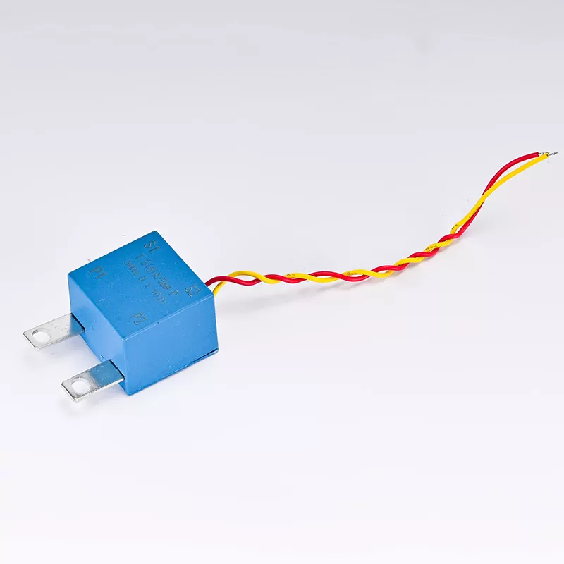
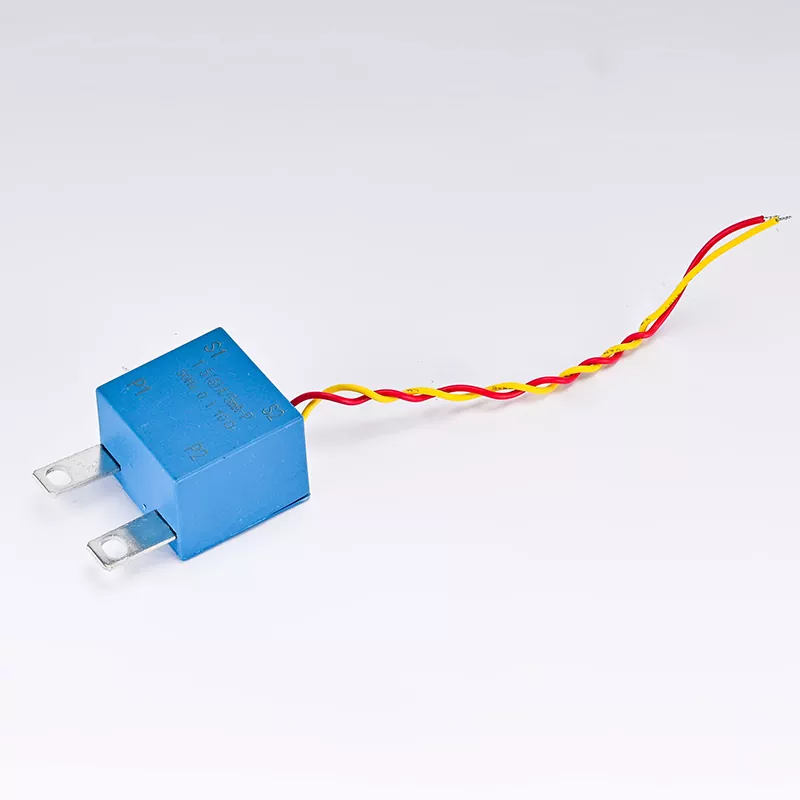
In principle, a current transformer (CT) is a device that converts large currents into small currents, and it works based on the principle of electromagnetic induction. In power systems, CTs are often used to measure large currents to protect and control circuits. The primary winding of a CT is directly connected in series in the circuit, while the secondary winding is connected to a measuring instrument or protection device. When current passes through the primary side, a corresponding current is generated on the secondary side according to the principle of electromagnetic induction. A voltage transformer (VT) is a device that converts high voltage into low voltage, also based on the principle of electromagnetic induction. VTs are used to measure high voltages in power systems to ensure safety and accuracy. The primary winding of a VT is connected in parallel in the circuit, while the secondary winding is connected to a measuring instrument or protection device. When there is voltage on the primary side, a corresponding voltage is generated on the secondary side according to the principle of electromagnetic induction.
The two have different measurement targets. Current transformers are mainly used to measure current for monitoring and protection of power systems. They can be used for current measurement, energy metering, short-circuit protection, and overload protection. The output current of CT is usually standardized to 5 amperes or 1 ampere to be compatible with standard measuring instruments and protection devices.
Voltage transformers are mainly used to measure voltage for monitoring and protection of power systems. They can be used for voltage measurement, energy metering, insulation monitoring, and overvoltage protection. The output voltage of VT is usually standardized to 100 volts or 100/√3 volts to be compatible with standard measuring instruments and protection devices.
The two have different design focuses. Current transformers need to consider the safety of current when designing. Since CTs are directly connected in series in the circuit, they must be able to withstand the short-circuit current in the circuit. The primary side of the CT is usually designed with a larger cross-sectional area to reduce resistance and heat loss while ensuring safe operation under short-circuit conditions.
Voltage transformers need to consider voltage safety when designing. Since VTs are connected in parallel in the circuit, they must be able to withstand over voltages in the circuit. There is usually a high insulation strength isolation between the primary and secondary sides of the VT to ensure safe operation under high voltage conditions. In the application field, current transformers are widely used in various links of the power system, including power stations, substations and distribution networks. They can be installed on equipment such as transmission lines, transformers and motors to monitor and protect these equipment from overloads and short circuits. Voltage transformers are also widely used in various links of the power system, especially in situations where high voltages need to be measured and controlled. They can be installed in substations and distribution networks to monitor and protect power systems from over voltages and insulation faults.
In terms of error, the current transformer error mainly comes from the influence of magnetic saturation and secondary side load. In order to reduce the error, CT is usually designed with higher magnetic permeability and lower secondary side resistance. The accuracy of CT is usually between 0.2% and 0.5%, which is sufficient for most power system applications. The error of voltage transformer mainly comes from the influence of magnetic saturation and secondary load, as well as the insulation loss between primary and secondary sides. To reduce the error, VT is usually designed with high magnetic permeability and low secondary resistance, and high insulation strength materials are used. The accuracy of VT is usually between 0.2% and 0.5%, which is sufficient for most power system applications.
In terms of maintenance inspection requirements, current transformer maintenance usually includes checking the connections of the primary and secondary sides, and ensuring that the CT is not magnetically saturated or damaged. Calibration of CT is usually performed after installation and during regular maintenance to ensure the accuracy of measurement. Maintenance of voltage transformer usually includes checking the connections of the primary and secondary sides, and ensuring that the VT is not magnetically saturated or damaged. Calibration of VT is usually performed after installation and during regular maintenance to ensure the accuracy of measurement.
We use cookies to offer you a better browsing experience, analyze site traffic and personalize content. By using this site, you agree to our use of cookies.
Privacy Policy