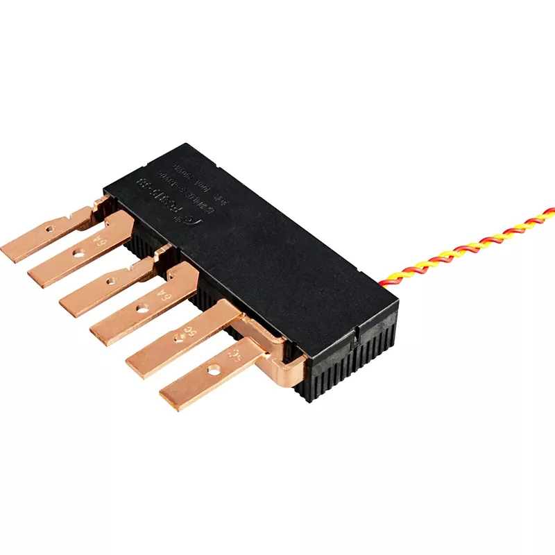
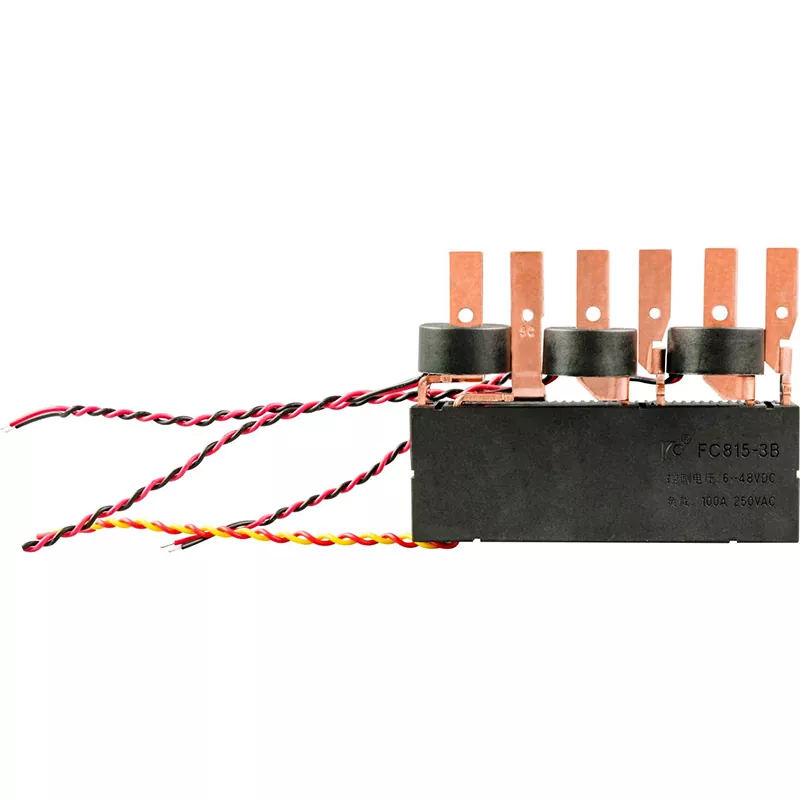
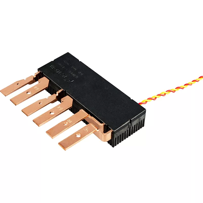
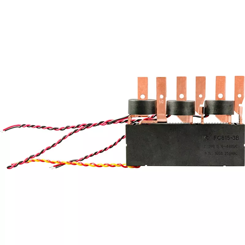
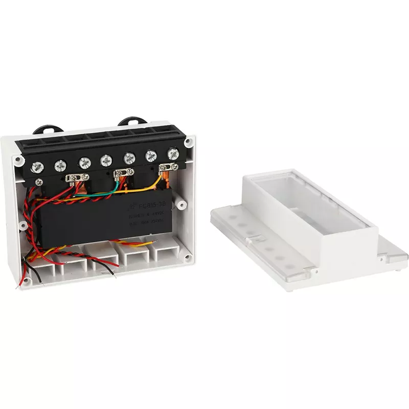
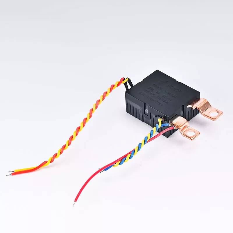
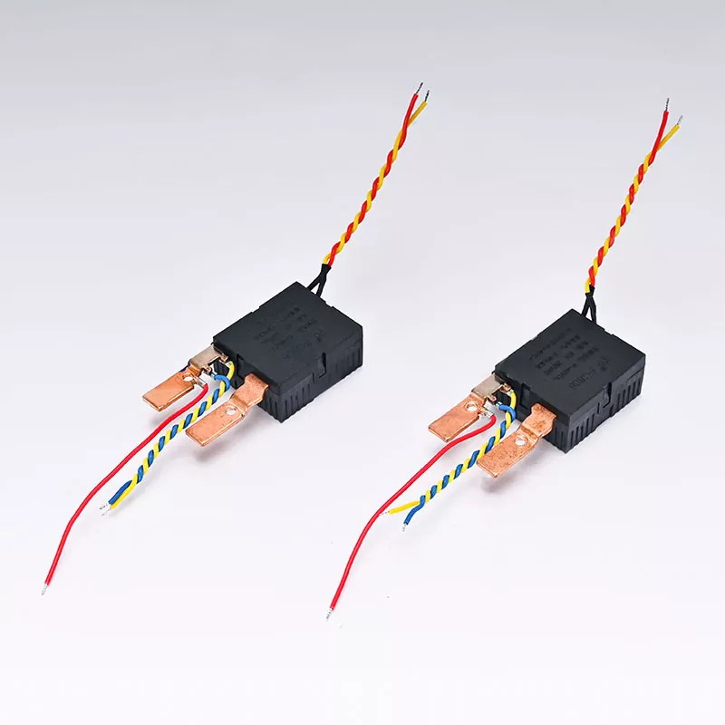
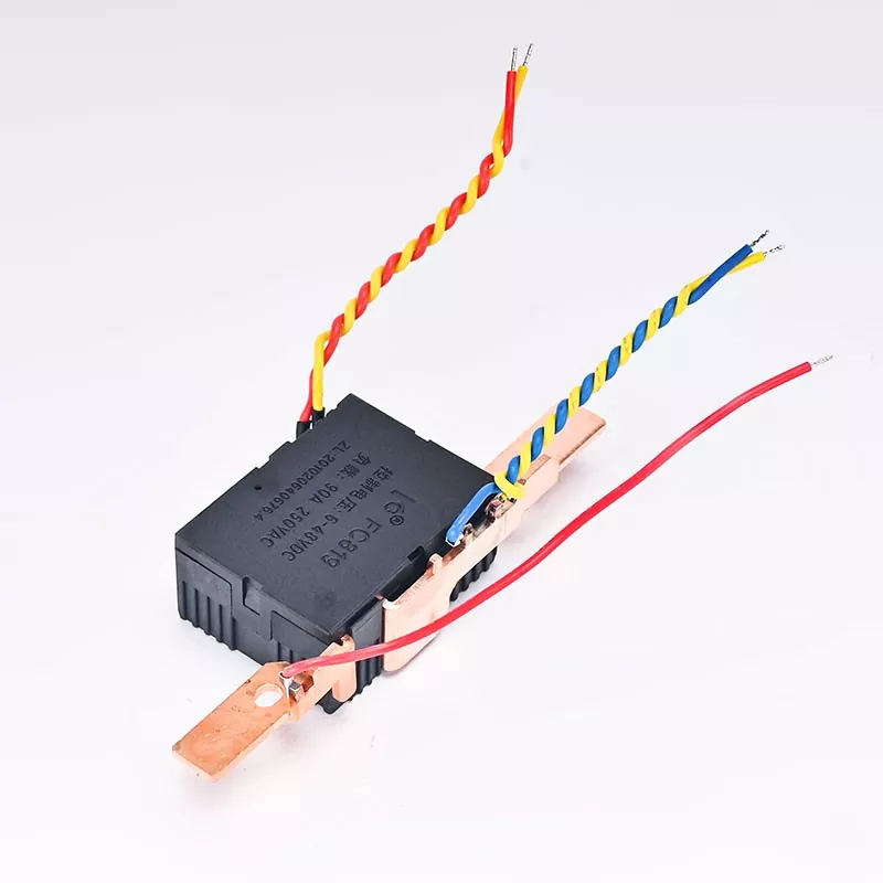
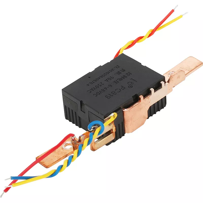
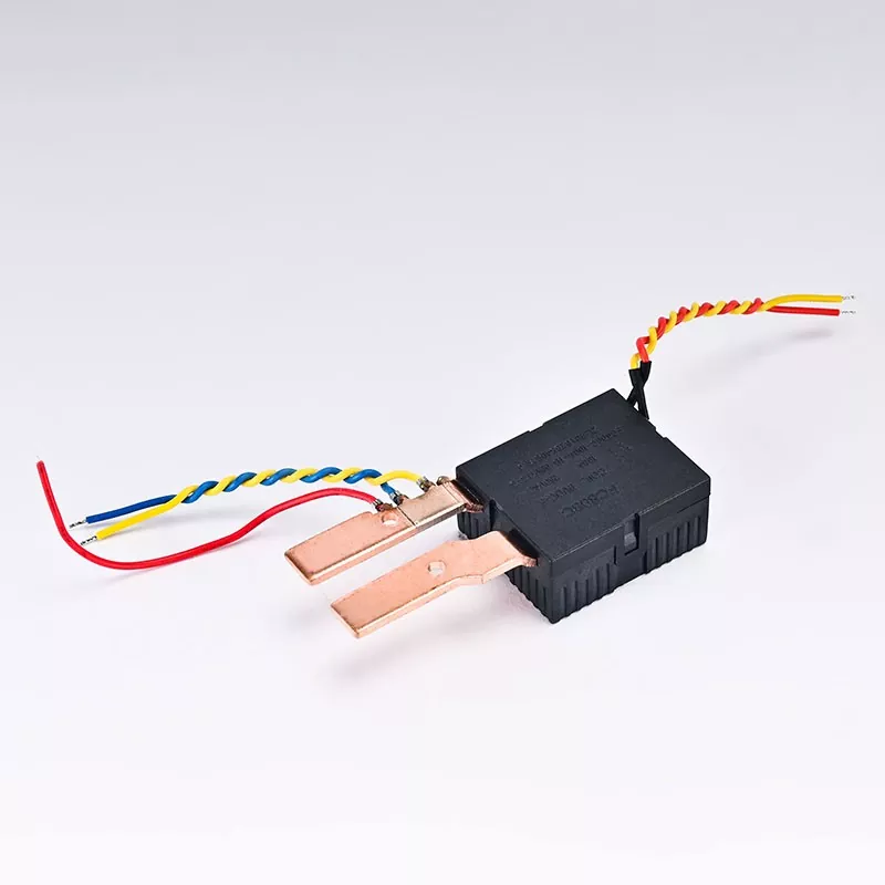
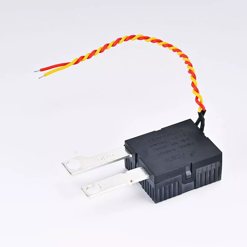
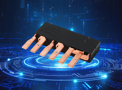
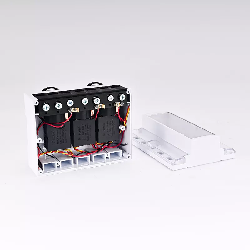
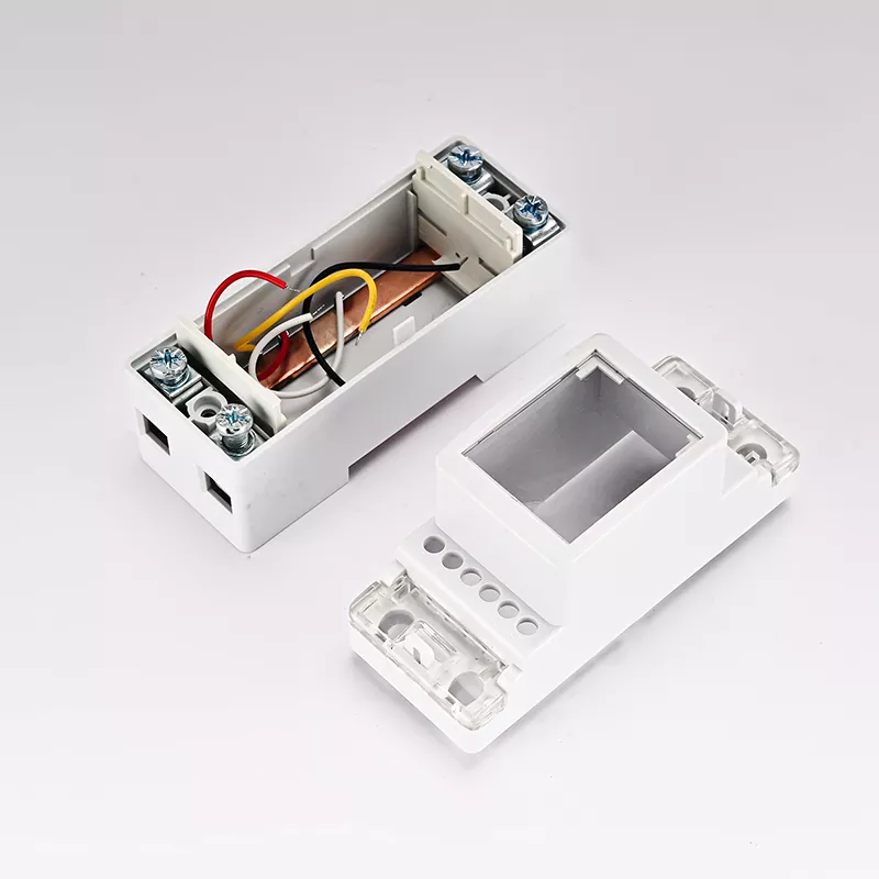
FACE is a professional manufacturer and supplier of magnetic latching relays, officially launching the 100A Latching Relay, model FC815-100A-(6-48)V-3B-DG7. Featuring a 3B configuration with three normally closed contact groups and silver alloy contacts, this relay delivers a switching capacity of 100A at 250VAC. It is designed for demanding applications such as smart meters, energy management and industrial control, where zero-power state retention and high reliability are essential. Factory-direct supply, OEM/ODM customization and worldwide shipping are available.
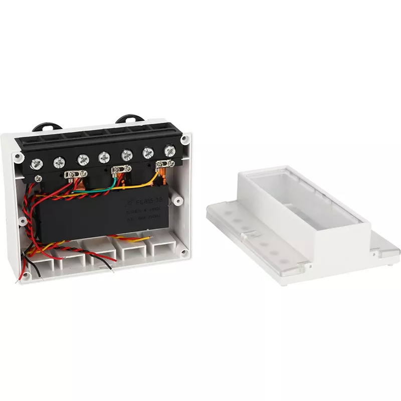
FACE's 100A Latching Relay, model FC815-100A-(6-48)V-3B-DG7, is designed for high-current switching applications, covering key uses such as remote connection and disconnection in smart meters, photovoltaic inverter isolation and power control in EV charging stations.
Unlike conventional electromagnetic relays that require continuous coil power to maintain their operating state, the FC815-100A-(6-48)V-3B-DG7 magnetic latching relay uses a permanent magnet to mechanically retain its contact position. A short pulse is sufficient to switch the contact state, after which the relay consumes no holding current. This makes it a preferred solution for energy metering equipment where every milliwatt of power consumption matters.
What distinguishes this model is its 3B contact configuration. Three independent normally closed contact groups are integrated into one compact housing, with each group rated at 100A at 250VAC. For smart meter manufacturers upgrading from single-channel to multi-channel switching, this means fewer components, reduced PCB space and lower assembly costs.
Key Advantages
1. Zero-Power Magnetic Latching
The permanent magnet mechanically locks the contact position. After switching, the coil consumes no additional power to maintain the state. This 100A Latching Relay is an ideal choice for battery-powered equipment and smart electricity meters.
2. 100A High-Current Capability
Rated at 100A and 250VAC, the relay supports a maximum switching power of 25,000VA. Silver alloy contacts ensure a low contact voltage drop of ≤15mV (at 10A), helping minimize heat generation even under long-term high-current operation.
3. Three Normally Closed Contact Groups
Three independent normally closed contact groups are integrated into one device, significantly simplifying PCB design for multi-phase electricity meters. One FC815-100A-(6-48)V-3B-DG7 relay can replace three single-channel relays, potentially reducing the BOM component count and PCB space requirements by up to 60%.
4. Wide Coil Voltage Range
Available coil voltage specifications include 6VDC, 9VDC, 12VDC, 24VDC and 48VDC. Single-coil and dual-coil versions are available. The dual-coil version provides independent set and reset control, making it suitable for fail-safe designs.
5. 6,000VAC Dielectric Strength
The insulation between contacts and coil withstands 6,000VAC (50/60Hz, 1 minute), exceeding the requirements of the IEC 62055-31 smart meter standard. Dielectric strength between contacts is 1,500VAC.
6. Adaptability to Extreme Environments
The relay operates at temperatures from -40°C to +70°C, with relative humidity of 45%–90% RH and shock resistance of 98m/s². From Nordic winters to Southeast Asian rainy seasons, it has been extensively validated in outdoor smart meter applications worldwide.
Technical Specifications and Contact Ratings
Parameter
Specification
Contact Configuration
3B (3 groups, normally closed)
Contact Material
Silver Alloy
Rated Contact Load
100A @ 250VAC
Maximum Switching Voltage
250VAC
Maximum Switching Current
100A
Maximum Switching Power
25,000VA
Contact Voltage Drop (@ 10A)
≤15mV
Mechanical Life
5 × 10⁵ operations
Electrical Life
1 × 10⁴ operations
Coil Specifications (20°C)
Rated Voltage (VDC)
Single-Coil Resistance (±10%)
Dual-Coil Resistance (±10%)
Single-Coil Power (W)
Dual-Coil Power (W)
Set Voltage (VDC)
Reset Voltage (VDC)
Maximum Permissible Voltage (VDC)
6
12.8Ω
6.4Ω × 2
2.80
5.60
≤4.2
≤4.2
30
9
28.9Ω
14.5Ω × 2
2.80
5.60
≤6.3
≤6.3
48
12
51.4Ω
25.7Ω × 2
2.80
5.60
≤8.4
≤8.4
60
24
205.7Ω
102Ω × 2
2.80
5.60
≤16.8
≤16.8
120
48
822.8Ω
411.4Ω × 2
2.80
5.60
≤33.6
≤33.6
240
General Characteristics
Parameter
Specification
Set Time
≤30ms
Reset Time
≤30ms
Dielectric Strength (Contact to Coil)
6,000VAC / 50–60Hz / 1 minute
Dielectric Strength (Contact to Contact)
1,500VAC / 50–60Hz / 1 minute
Insulation Resistance (500VDC)
≥1,000MΩ
Operating Temperature
-40°C to +70°C
Relative Humidity
45%–90% RH
Vibration Resistance
10–55Hz, 1.5mm amplitude
Shock Resistance
98m/s²
Weight
Approx. 140g
Typical Applications
The FC815-100A-(6-48)V-3B-DG7 magnetic latching relay is designed for critical applications requiring high-current switching, zero-power state retention and long service life.
1. Smart Electricity Meters (AMI/AMR)
Remote connection and disconnection control in single-phase and three-phase smart electricity meters. The 3B configuration can simultaneously switch the L1, L2 and L3 phase circuits.
2. Photovoltaic and Energy Storage Systems
AC-side isolation in photovoltaic inverters, battery pack disconnection and anti-islanding protection circuits.
3. Electric Vehicle Charging
Power relays for AC charging stations. The magnetic latching design eliminates standby power consumption, helping meet the requirements of the latest energy efficiency regulations.
4. Industrial Control
High-current load switching in PLC control systems, motor control cabinets and power distribution units.
5. Smart Homes and Building Automation
Main power connection and disconnection control in whole-home energy management systems.
6. Telecommunications Power Systems
Battery disconnection units and rectifier isolation in 48VDC telecommunications power systems.
Frequently Asked Questions
Q1: What is the difference between single-coil and dual-coil versions?
A: The single-coil version uses one coil to perform both set and reset operations through pulses with opposite polarities. This results in a simpler drive circuit and fewer PCB traces.
The dual-coil version has separate set and reset coils, allowing independent control without polarity reversal. This simplifies the control logic.
Single-coil versions are the most common choice for smart meter applications, while dual-coil versions provide additional reliability for fail-safe industrial control designs.
Q2: Can this 100A Latching Relay withstand surge currents above 100A?
A: The rated switching current is 100A at 250VAC. Short-duration surge currents, such as those generated during motor startup or capacitor charging, can temporarily exceed this rated value. The silver alloy contacts provide the capability to withstand instantaneous overloads.
However, if an application involves continuous currents above 100A or extremely high surge currents, we recommend considering a 120A model or contacting our engineering team for guidance based on the specific application.
We have accumulated more than ten years of field data from magnetic latching relay deployments in 52 countries worldwide. Each rated specification is supported by extensive engineering validation.
Q3: What is the difference between 3B and 3A configurations?
A: 3B indicates three normally closed (NC) contact groups. All contacts are closed in the relay's initial state. This is a standard configuration for smart electricity meters, where the default state is "powered on".
3A indicates three normally open (NO) contact groups, with contacts open in the initial state.
The FC815 series supports both configurations as well as mixed contact arrangements. Choose 3B if the required fail-safe default state is "powered on", or 3A if the required default state is "powered off".
Q4: Are samples available for testing before bulk orders?
A: Yes. We provide FC815-100A-(6-48)V-3B-DG7 samples for technical evaluation. The standard sample quantity is 2–5 units, shipped with freight collected.
For larger pilot evaluation batches, we can also accommodate specific testing requirements. Please contact us with your target coil voltage, coil type (single or dual) and application details so that we can arrange samples as quickly as possible.
Q5: What is the typical lead time for bulk orders?
A: The standard lead time for regular configurations is 10–15 days. Customized specifications, including non-standard coil voltages, special contact arrangements and customized markings, generally require 15–25 days depending on complexity.
As a manufacturer with fully integrated production capabilities, we maintain buffer inventory for commonly used configurations to support urgent orders. Please contact our sales team for further details.
We use cookies to offer you a better browsing experience, analyze site traffic and personalize content. By using this site, you agree to our use of cookies. Privacy Policy